rjdoles
Maxi-Scooter Rider


Number of posts : 141
Age : 76
Location : Columbus, Ohio
Points : 4630
Registration date : 2012-09-24
 |  Subject: Start Interlocks Subject: Start Interlocks  Sat May 04, 2013 10:53 pm Sat May 04, 2013 10:53 pm | |
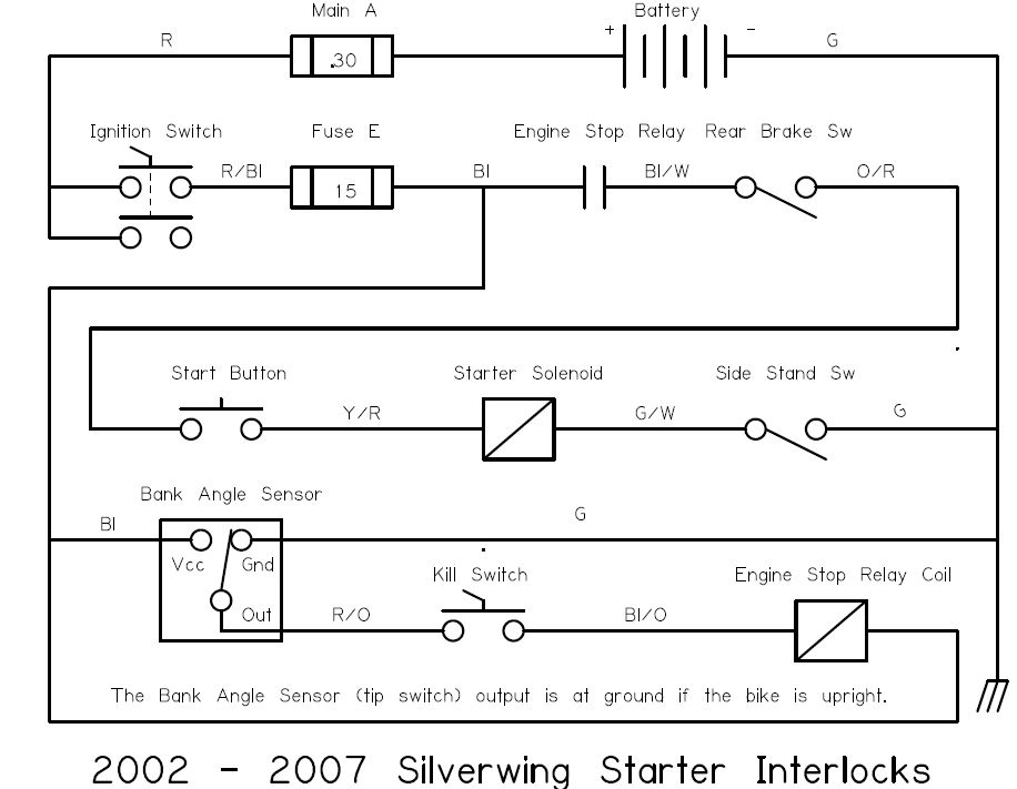
| The Honda service manual is great in most aspects. However, I nearly went blind trying to use a magnifying glass to follow the start interlocks on the schematic. I don't know why Honda decided to put the entire electrical diagram on a single page even if it was a double-wide, fold-out page. They could have broken the schematic up over several pages and increased the print size a bit so you wouldn't need an electron microscope to read it. There are frequent questions on this site about the bike not cranking. I decided to trace the starter motor interlock circuit. Wire colors are: R = red, R/Bl = red with black stripe, Bl = black, Bl/W = black with white stripe, O/R = orange with red stripe, Y/R = yellow with red stripe, G/W = green with white stripe, G = green. I hope that this drawing helps.  Ride safe!
Last edited by rjdoles on Thu May 09, 2013 3:37 pm; edited 15 times in total |
|
RArch
Silver Wing Expert


Number of posts : 613
Age : 57
Location : West London, UK
Points : 5414
Registration date : 2011-11-07
 |  Subject: Re: Start Interlocks Subject: Re: Start Interlocks  Sun May 05, 2013 6:53 am Sun May 05, 2013 6:53 am | |
| Thanks, that could be handy. I've saved it off and hope to never need it  |
|
Dimond
Silver Wing Expert


Number of posts : 540
Age : 79
Location : San Francisco Bay Area
Points : 5533
Registration date : 2011-08-07
 |  Subject: Re: Start Interlocks Subject: Re: Start Interlocks  Sun May 05, 2013 11:15 am Sun May 05, 2013 11:15 am | |
| - rjdoles wrote:
- I nearly went blind using a magnifying glass to try to follow the start interlocks on the schematic.
First off a mighty thanks for doing/sharing this! When the scoot won't turn over (happened to me) it can be a chore to diagnose the failure point - this will certainly help. I too have resorted to the magnifying glass - and enlarging my Honda Sevice Manual wiring schematic from 11x17 to 16x32 inches in size - more than a 2x enlargement - which when folded in quarters tucks nicely back in the manual - and don't need the magnifiying glass (but it helps). Having your schematic allows me to better understand what is going on BEFORE I look at the wiring diagram, as there are so many wires going so many places. I am amazed at the number of components that could fail - and how few do. When I work on my SWing I am appreciative of how well made it is - and how few component failures I have had. On another note, my schematic for a 2008 ABS SWing is 003Z-MCT-L700. On my diagram about midway from the bottom of the page - between the 'fan motor' and 'vehicle speed sensor', there are a bunch of horizontal lines - and after 3 lines up there are two lines that are disconnected (just stop - don't go anywhere). This has not proved to be a problem since I can figure out where they are supposed to go based upon the OTHER ABS diagram (pre-2008). Does your schematic have these same 'disconnected' lines? Have you found any other errors on your 003Z-MCT-L700 schematic? Thanks. |
|
honda_silver
Silver Wing Guru


Number of posts : 2453
Location : Georgetown, Tx
Points : 8372
Registration date : 2008-12-23
 |  Subject: Re: Start Interlocks Subject: Re: Start Interlocks  Sun May 05, 2013 1:32 pm Sun May 05, 2013 1:32 pm | |
| - rjdoles wrote:
- The Honda service manual is great in most aspects. However, I nearly went blind using a magnifying glass to try to follow the start interlocks on the schematic. I don't know why Honda decided to put the entire electrical diagram on one page even if it was a double-wide, fold-out page.
I scanned the two pages into two PDF pages. Then I select the option to display two pages side-by-side. Now I can increase the magnification to whatever level I need ... and use the cursor buttons to step in any direction. Since the Honda Service manual is copyrighted, I cannot share but anyone can do the same for themselves. |
|
rjdoles
Maxi-Scooter Rider


Number of posts : 141
Age : 76
Location : Columbus, Ohio
Points : 4630
Registration date : 2012-09-24
 |  Subject: Re: Start Interlocks Subject: Re: Start Interlocks  Mon May 06, 2013 10:55 pm Mon May 06, 2013 10:55 pm | |
| - Dimond wrote:
On another note, my schematic for a 2008 ABS SWing is 003Z-MCT-L700. On my diagram about midway from the bottom of the page - between the 'fan motor' and 'vehicle speed sensor', there are a bunch of horizontal lines - and after 3 lines up there are two lines that are disconnected (just stop - don't go anywhere). This has not proved to be a problem since I can figure out where they are supposed to go based upon the OTHER ABS diagram (pre-2008). Does your schematic have these same 'disconnected' lines? Have you found any other errors on your 003Z-MCT-L700 schematic? Thanks. Yes, there are some broken lines on my ABS schematics as well. There is also a disconnect on the right turn signal wiring. It almost looks like the missing/broken wires were a result of some cad sizing/scaling problem. |
|
