As discussed previously in other threads (here and on other boards), the Silverwing's flasher circuit is embedded into the instrument cluster instead of being a traditional/replaceable unit. Now, I won't pretend to be more intelligent than the Honda engineers, but that's a bone-headed move that makes any service and upgrading difficult at best. If the built-in flasher circuit ever fails (not very likely), then the entire instrument cluster must be replaced. That's just about as annoying as trying to remove the left glove box lid.

I decided to upgrade all of the indicator lights on my scoot to LED's. Unfortunately, the LED's draw too little current for the factory flasher to operate at the correct rate, which leads to the hyper-flash problem (fast flash, like when one of the bulbs is out). Since the factory flasher isn't a replaceable item, the only alternatives that I can fathom are:
- Use load resistors, which takes away the benefit of the lower current draw of the LED's, or
- Make a bypass harness at the instrument cluster that intercepts the inbound switch wires and outbound signal wires.
I decided to go with option #2 and make the bypass harness because that will let me use an external flasher module and make clean extensions for additional front signal outputs (e.g. mirror signal LED's, etc). This will also give the ability to bridge both left and right circuits to create 4-way hazard flashers. Other possible upgrades on this path could include auto-cancelling signals, audible beeper/buzzer, etc.
The bypass needs to be done at the back of the instrument cluster because that's the only convenient place to intercept the switch wires before the factory circuit and outbound signal wires in the same place. The only drawbacks that I can see are:
- The factory circuit allows for front running lights (it runs them at about 10.2 volts until a signal is activated, then goes full on/off); the new circuit could certainly incorporate that, but I haven't gotten that far yet.
- Pilot indicators need to be fed back into the instrument cluster in the OEM locations or somewhere nearby; not sure if I can use the factory turn indicators without powering the whole OEM circuit (they are SMD LED's, directional flow), so additional LED's might need to be drilled in somewhere.
Alternately, the front signal bulbs (BAU15S type) and sockets could be replaced with dual-filament (7443 type) and scrap the low-voltage bit entirely. But again, I haven't gotten that far and that would also require some minor fairing harness changes for the additional signal wire to each side.
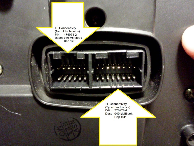
I searched for quite a while to locate the exact AMP connectors that are used on the factory harness. The only visible marking on the connectors is "AMP", but no part number. So, after days of searching online catalogs and cross-references, I found the exact OEM part in Tyco Electronic's vast arsenal of connectors.
The male and female connector housings are around USD $1.20-1.80/ea (2 per harness) and the internal terminals and receptacles are around $0.30/ea (56 per harness). The next hurdle is that all of the suppliers for these parts have HUGE minimum order requirements... try 1000-5000 pieces, some are as high as 20K pieces for their minimum. Ouch. Tyco Electronics (Amphenol) was kind enough to send me a few "engineering samples" so I could prototype the harness.
My next step is to get a working sample and then... maybe Dennis could build them if anyone is interested? I could do it, but I'm not properly tooled up for the task. I'm sure Dennis can attest that the tooling is not cheap if you want to do it right. After all, I wouldn't want a poor-quality connection causing my instrument cluster to wink out at random... that would be a Bad Thing.
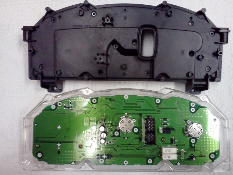
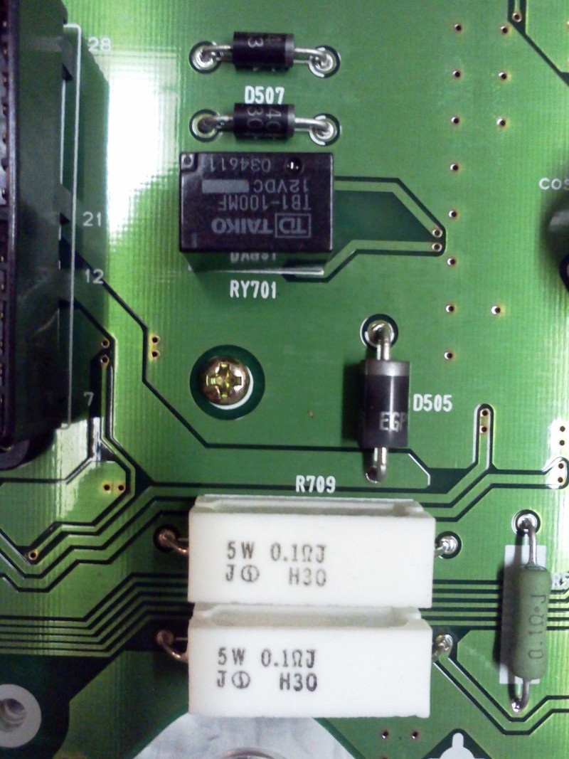
Well, enough of what I don't have or haven't done yet... here are a few pics of the interior of the instrument cluster where the dreaded flasher bug lives, and others of the male and female connectors needed. Later, I will post the connector pin numbers instead of wire colors because the Honda color codes on the small harnesses are very difficult (stripes, dots, slashes, and bands... whew).
Here is the instrument cluster opened, face-down, showing the back of the circuit board:

This is a close-up of the flasher relay, diodes, and load resistors for the front running light function (presumed):

This is the back of the instrument cluster. I have annotated the picture with the equivalent TE/AMP connector numbers for wire-to-wire use (the cluster uses a wire-to-board connector, different p/n):

This is a shot of the bike harness connectors for the gauge cluster. Again, I have annotated the picture with the TE/AMP part numbers:

