I have always been interested in how the charging system for motorcycles work. I was also curious about how motorcycle charging systems were different from those for automobiles. I have done some Internet research on both and I have also combed through the Swing service manual for information specific to it. I tried to organize the information here. I hope that there are other Swing enthusiasts that might have an interest in it and that they find it useful.
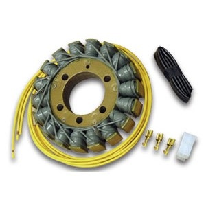
The Silverwing has a 3 phase A.C. generator. The stator consists of coils of enamel insulated wire wound around the 18 poles of a laminated iron core.

The rotor consists of a spool with some powerful permanent magnets embedded into it. The rotor spool is mounted on the end of the crankshaft. With the engine running, the spinning magnets produce an alternating current in the three yellow output wires from the stator. The alternator would produce a low power output at idle. The output would increase as engine rpm increases up to a peak of 441 watts at 5000 rpm. The 441 watt output works out to approximately 30 amps at 14 volts. The size of the wire that was used in the stator is designed to limit the current to 30 amps. Trying to apply a load that is larger than 30 amps will result in the alternator voltage dropping off dramatically. This characteristic is used by the Swing regulator for voltage control.
Automobiles alternators use a much better but more complicated system. Instead of permanent magnets, the rotor consists of rotating coils of wire that the regulator powers through a pair of brushes and slip-rings. The brushes and slip-rings are similar to the brushes and armature that is found in an electric drill motor.
By varying a small current of a few amps through this rotor coil, the automobile regulator can control the alternator output which could be as much as 120 amps on some vehicles.
At idle, the voltage regulator would supply more current to the rotor. This would boost the alternator output to produce a significant charging current at idle. This is something that our Swing's don't do. As the rpm’s increase, the regulator would adjust the rotor current to maintain the output voltage at about 14.5 volts.
The slip-rings are the weak link in this type of alternator. Alternator slip-rings or generator brushes were used on some early motorcycles and they were problematic. Since our power requirements are only a few hundred watts, motorcycle engineers chose the simpler and more reliable permanent magnet rotor arrangement. The problem with the permanent magnet method is that the alternator output cannot be controlled. The alternator output voltage and current will both increase with an increase in rpm. If disconnected from the regulator, and measured across any two of the three yellow wires, our alternator may produce 16 volts A.C. at idle increasing to over 60 volts A.C. or more at 5000 rpm. The motorcycle regulator components had to be sized to control the 30 amp output of the alternator. The regulator is designed to add enough of a load to drop the output voltage to the 14 volt range. Keep in mind that the Swing alternator only produces 30 amps and not the 40 to 120 amps available from the automobile alternators.
The schematic shows a typical motorcycle charging system.

The three yellow wires from the alternator are connected to the rectifier/regulator. Those yellow wires go to the six diodes in this diagram. The diodes convert the alternating current (A.C.) from the alternator to the direct current (D.C.) that is required to charge the battery.
This is the alternator output waveform (3 phase A.C. voltage) for one crankshaft rotation.

The voltage swings from positive to negative once for each rotation of the crankshaft. The coils are 120 degrees apart so they are at 0 volts at different crank degrees.
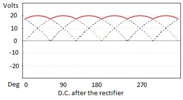
This is the output from the alternator after the rectifiers convert it to D.C. The rectifiers take the negative half of the waves that you see on the waveform above and invert them. It makes them positive so the result is double the number of positive waves.

There are also three SCR’s (Silicon Controlled Rectifier) in the regulator. SCR’s are fast electronic switches. There is one SCR for the output from each of the yellow wires. When one of the SCR’s is switched on, the current from one phase (yellow wire) is shorted to ground lowering the alternator output voltage.
This is the alternator output with one SCR firing. Notice how there is a dip in the alternator output. The black vertical line is when one SCR switched on and the rest of that waveform is missing as it was switched to ground.

The regulator monitors battery voltage and switches these three SCR’s on to regulate battery voltage. The SCR’s can be switched on earlier or later in each cycle to vary the power that is sent to ground. This is similar to the way a light dimmer can be adjusted to allow a portion of the A.C. to reach a lamp. The SCR’s were sized large enough to switch the entire 30 amp capability of the alternator. The regulator has a finned heat sink to dissipate the heat that is produced from switching the SCR’s on.
The Silverwing typical base load is as follows:
Headlight 55 watt high beam (normally off)
Headlight 55 watt low beam (normally on)
Brake / tail light lamp 21 watt brake (normally off) / 5 watt taillight (normally on) two lamps
Front turn lamps 21 watts each (normally on) two lamps
Rear turn lamps 21 watts each (normally off) two lamps
License light 5 watts
Fuel pump estimate 10 watts ?
ECM estimate 10 watts ?
Ignition coils estimate 60 watts each ?
Total base load is approximately 252 watts. The alternator maximum output is 441 watts. Subtract the base load from the alternator output results in 189 watts remaining to run accessories and to charge the battery.
With a low battery, any current the alternator produces above the 252 watt base load would be used to charge the battery.
With a fully charged battery, the regulator switches on the SCR’s earlier to dump the extra 189 watts to ground.
Troubleshooting the charging system.
1. Recurring dead battery problems could be the battery. Have it checked under load at an auto parts store or battery vendor.
2. If the battery checks good.
a. Place the Swing on the centerstand.
b. Connect a multimeter set to the 20 Volts D.C. range across the battery terminals. The voltage with the engine off for a fully charged battery should be about 12.6 volts.
c. Start the engine and with the engine running at idle the voltage across the battery should increase from 12.6 volts to about 14 volts.
d. Increase the engine speed and observe if the voltage remains at about 14 volts. If it does then the charging system is working OK.
3. If you don’t get these voltage readings then there may be a problem with the alternator (stator) or the voltage rectifier/regulator.
a. Disconnect the connector to the stator (3 yellow wires).
b. Set the multimeter to the 200 ohm resistance range.
c. Label the three yellow wires 1, 2, 3. It doesn’t matter which wire is which number.
d. Measure the resistance between 1 and 2. It should read .1 to .5 ohms.
e. Measure the resistance between 2 and 3. It should read .1 to .5 ohms.
f. Measure the resistance between 1 and 3. It should read .1 to .5 ohms.
g. Measure from each of the 3 leads to a chassis ground point on the Swing. Each should have a very high resistance reading or open circuit (no ground reading).
4. Connect a multimeter that is set to the 200 A.C. volt range to two of the alternator leads. Start the Swing.
a. At idle, the voltage reading across alternator leads 1 and 2, 2 and 3 or 1 and 3 should be about 16 volts.
b. Increase the rpm and the voltage should increase.
5. If the readings in steps 3 and 4 were good then the stator is good and the regulator/rectifier is probably bad.
Battery charging
The Silverwing service manual recommends a quickcharge of less than 5.5 amps. It also recommends a trickle charge of 1.1 amps or less.
Driving to charge the battery.
Type of driving will affect the battery charging time. Stop and go driving will result in a lower average charge and longer charging time. Freeway driving will result in a higher alternator output and a shorter charging time.
Accessories like heated gloves, additional lights etc. will reduce the current available to charge the battery. Since the output of the alternator is low at idle, a lot of time at idle with electrical accessories on could result in draining the battery.
Jump Starting
The Honda owners manual states that they do not recommend jump starting the Silverwing. If you must jumpstart a Silverwing, make sure that the donor vehicle engine is not running.
The reason for this is that a running vehicle may damage the Silverwing regulator. If the donor vehicle alternator output voltage happened to be higher (say 14.5 volts) than the Silverwing regulator output (say 14.2 volts), the Silverwing regulator would attempt to load down the voltage to 14.2 volts. The car alternator / battery is capable of supplying far more than 30 amps and the Silverwing regulator’s 30 amp rated SCR’s would be destroyed. With the vehicle switched off, the donor battery voltage of 12.6 would be adequate to start the scooter and unless the jumper leads were reversed, could not damage the regulator.
Ride safe!
